Spatial intelligence guide
How to Create a Site Context Map for Architecture Projects
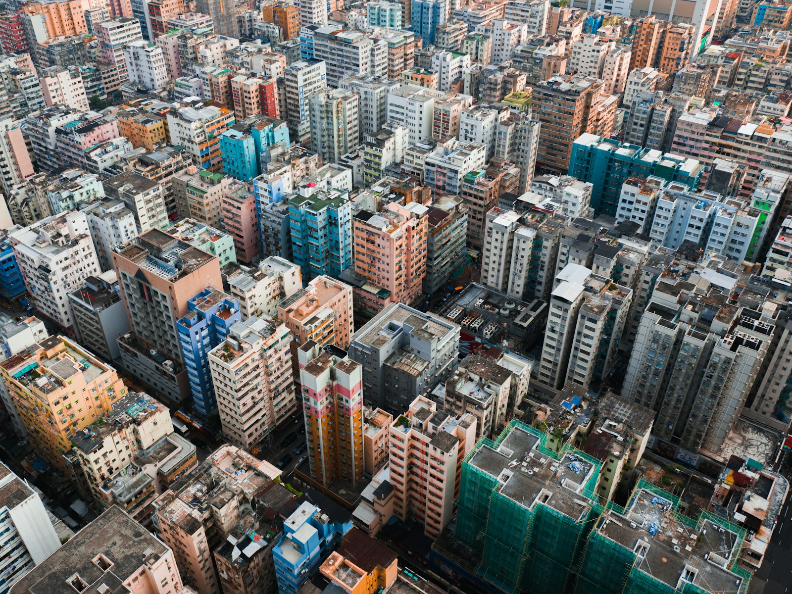
Before designing a building, architects need to understand the site.
What surrounds it?
Where are the streets?
How dense is the existing development?
Where are the parks and public spaces?
What buildings are immediately adjacent?
A site context map is one of the simplest and most useful ways to answer these questions.
The problem is that creating one manually can take much longer than the analysis itself.
You may need to find a base map, download building footprints, collect roads, identify green spaces, clean the data and prepare everything for a presentation or CAD workflow.
With a spatial analysis tool such as Aino, you can start with the site location and build the context map from sourced geographic data.
Here is a simple workflow.
What is a site context map?
A site context map shows the physical and urban environment surrounding a project site.
A basic architectural context map usually includes:
the project site;
surrounding buildings;
streets;
pedestrian paths;
parks and green spaces;
public spaces;
nearby infrastructure.
The purpose is not to produce a finished architectural drawing.
It is to create a clear picture of the existing context before design begins.
Scenario: You are starting a new architecture project
Imagine you have just received a new project.
You have:
a site address;
a site boundary;
perhaps a survey;
very little information about the surrounding area.
Before beginning the concept design, you want a map covering approximately 500 metres around the site.
You want to understand the urban fabric.
The traditional workflow
You might:
1. Open Google Maps or another mapping service. 2. Search for the site. 3. Find a GIS data source. 4. Download building footprints. 5. Download roads. 6. Find parks and green spaces. 7. Import everything into GIS. 8. Clip the data. 9. Style the layers. 10. Export the map.
For an experienced GIS user, this is straightforward.
But it is still a lot of preparation for a relatively simple question:
“What’s around my site?”
Step 1 — Define the site
Start with the project location.
You can use an address or geographic location as the center of the analysis.
Then define the area you want to understand.
For example:
Immediate context: 100–200 m
Local context: 500 m
Broader urban context: 1 km
There is no universal correct radius.
The right scale depends on the project.
A small infill building may require a very detailed 200-metre context.
A masterplan may require several kilometres.
Step 2 — Add the building footprints
Buildings are usually the first layer architects want to see.
Building footprints help reveal:
urban density;
block structure;
building orientation;
setbacks;
open space;
surrounding massing.
For example, a site surrounded by tightly packed buildings tells a very different urban story from one surrounded by detached buildings.
The footprint layer gives you this information immediately.
You can then ask more specific questions:
“How dense is the development around the site?”
or:
“Where are the largest open spaces?”
Step 3 — Add the street network
Next, add streets and paths.
This reveals the site’s relationship with the movement network.
Look for:
major roads;
local streets;
pedestrian paths;
intersections;
dead ends;
potential access points.
For an architect, this can immediately inform early questions around:
vehicle access;
pedestrian access;
entrances;
frontage;
street hierarchy;
public realm.
Again, the objective is not to replace a detailed transport study.
It is to establish the spatial context quickly.
Step 4 — Add green space and public space
Green space is another useful contextual layer.
Add:
parks;
gardens;
recreational areas;
public open spaces;
other mapped green areas.
Now the map starts to communicate more than just geometry.
You can see how the site relates to the city’s open-space network.
For example:
Is the site next to a park?
Is there a green corridor nearby?
Are there large public spaces within walking distance?
Is the surrounding neighbourhood mostly built-up?
These observations can become part of the early design strategy.
Step 5 — Style the map for architecture
A good site-context map should not look like a database.
The purpose of styling is to make the spatial relationships obvious.
A simple hierarchy might be:
Site
↓
Buildings
↓
Roads
↓
Green space
↓
Other context
You do not need dozens of colours or symbols.
The map should answer the question:
What matters around this site?
Example prompt
With a natural-language spatial analysis workflow, you could start with something as simple as:
“Create a site context map showing building footprints, streets, pedestrian paths, parks and green spaces within 500 metres of this site.”
Then refine it:
“Keep the site boundary separate.”
“Show major streets more prominently.”
“Export the building and street layers for CAD.”
The important part is that you are describing the analysis you want, rather than manually constructing every GIS operation.
What should the final map contain?
For a basic architectural site context map, aim for five or six layers:
Layer · Why it matters
Site boundary · Defines the project
Buildings · Shows urban fabric
Streets · Shows movement and access
Pedestrian paths · Shows walkability
Parks / green space · Shows open-space context
Key infrastructure · Adds relevant context
You can always add more later.
Starting simple is usually better.
What can you learn from the map?
Once the layers are together, several patterns become visible.
Urban grain
Are the surrounding blocks fine-grained or large?
Density
Is development compact or dispersed?
Access
Which streets connect directly to the site?
Open space
Where are the largest green or public spaces?
Frontage
Which edges of the site face streets or public spaces?
Adjacencies
What buildings and uses immediately surround the site?
These observations can become the basis for the next stage of architectural analysis.
Export the map into your design workflow
A site context map is most useful when it does not stay trapped inside a mapping application.
If you are working in Rhino or AutoCAD, you may want the underlying geometry.
Aino supports spatial export workflows including DXF and GeoJSON for relevant site-analysis layers.
That means the context can become part of the working design environment rather than simply being a screenshot.
For example:
Aino
→ building footprints
→ streets
→ site boundary
↓
DXF
↓
Rhino / AutoCAD
↓
Design development
This is particularly useful during early massing and urban-design studies.
Keep the map separate from the design
One common mistake is trying to make the context map do everything.
You do not need:
every POI;
every road classification;
every piece of infrastructure;
dozens of labels.
The context map should provide a clean spatial foundation.
Then create additional maps for specific questions.
For example:
Site context map
Accessibility map
Land-use map
Density map
Environmental map
Each map answers a different question.
When should architects make a site context map?
A site context map is useful at almost every stage of a project.
Concept stage
Understand the urban setting.
Site analysis
Identify important spatial relationships.
Massing
Understand surrounding building patterns.
Urban design
Study streets, blocks and public space.
Client presentation
Explain the site’s context visually.
Competition work
Communicate the design problem quickly.
A simple 10-minute workflow
If you want a repeatable process, use this:
1. Locate
Find the project site.
2. Define
Choose a 200–500 m analysis radius.
3. Add
Buildings + streets + paths + green space.
4. Filter
Remove layers that do not contribute to the question.
5. Style
Create a clear visual hierarchy.
6. Analyse
Look for density, access, open space and adjacency.
7. Export
Move useful geometry into your CAD workflow.
That is enough for a strong first-pass site context analysis.
Final takeaway
A site context map does not need to be complicated.
The goal is simply to answer:
“What is around my project site, and how does the site relate to it?”
Start with:
Buildings + Streets + Paths + Green Space + Site Boundary.
Then add more data only when it helps answer a specific design question.
With Aino, the workflow can start from a natural-language request, use sourced spatial data to build the context, and export relevant geometry for further work.
The result is not just a prettier map.
It is a faster way to get from:
“I have an address.”
to:
“I understand the urban context.”
FAQ
What is a site context map?
A site context map shows the buildings, streets, paths, green space and infrastructure around a project site so architects can understand the existing setting.
What layers should a site context map include?
A basic context map should include the site boundary, surrounding buildings, streets, pedestrian paths, parks, green space and key infrastructure.
Why export site context geometry to CAD?
CAD-ready exports let architects reuse sourced spatial geometry in Rhino, AutoCAD or GIS workflows instead of redrawing context from screenshots.
What practitioners say
“Aino produced the context layers we needed before our first massing review.”
— Oliver, Architecture Partner
Further reading and resources
Continue with related Aino guides, product pages and documentation: